| Novatech

F300 Sideload Rejection Loadcell

Standard Ranges 1, 2, 5, 10, 20, 50, 100, 200 and 400kN (100kgf to 40tonnef)

  • High performance
  • Misalignment error compensation
  • Excellent Sideload rejection < 1%RL error for 20%RL transverse loads and much less for vectors
  • Formulaic error quantification
  • Traceable calibration with certificate included in the standard price
  • Standard 1 year warranty

Specification

Parameter

Value

Unit

Non-linearity - Terminal

±0.03

% RL

Hysteresis

±0.03

% RL

Creep - 20 minutes

±0.05

% AL

Repeatability

±0.02

% RL

Rated output - Nominal

1.2

mV/V

Rated output - Rationalised

1.0

mV/V

Rationalisation tolerance (applies to single direction calibrations)

±0.1

% RL

Output symmetry

±0.2

%AO

Fatigue life

108

±RL cycles

Zero load output

±4

% RL

Temperature effect on rated output per °C

±0.005

% AL

Temperature effect on zero load output per °C

±0.01

% RL

Temperature range - Compensated

-10 to +50

°C

Temperature range - Safe

-10 to +80

°C

Excitation voltage - Recommended

10

V

Excitation voltage - Maximum

20

V

Bridge resistance

700

Ω

Insulation resistance - Minimum at 50Vdc

500

MΩ

Overload - Safe

100

% RL

Overload - Ultimate

200

% RL

Maximum permissible sideload

60

% RL

Maximum permissible moment

See reference chart in E036

Sealing

IP65

Weight - Nominal (excluding cable)

See outline drawing

Benefiting from advanced machining techniques, the F300’s complex beam structure offers reliable error compensation in a cylindrical, 'donut' style footprint.

Whereas the long established 'donut' products such as the F202 require near perfect loading conditions, the F300's unique strain system compensates for typical axial misalignment as well as the combination of large sideloads and small moments. This has been used to good effect in ‘Junkers’ test machines, subjected to an extreme, rapid cycling of large sideloads, for bolt tension and 'self-loosening' fastener tests. Further details of this application, along with simple error equations for the F300 loadcell can be found in Engineering Sheet E036.

The circular patterns of fixing holes are deliberately over engineered to withstand potentially large moment effects and allow tension, compression and bi-directional versions as standard. There is also the added potential for customer supplied adaptor plates to give versatile end fixing options. Note that care should be taken to ensure the correct lengths of screws are used and that these are torqued correctly as given in Engineering Sheet E036.

We are happy to design variants of this loadcell to meet your specific requirements. Ranges above 5kN can be manufactured for fully compensated operation up to +250°C. Please consult our engineering department for further information.

Order Codes

Code

Description

F300CFR0K0

Compression, unrationalised

F300TFR0K0

Tension, unrationalised

F300UFROK0

Bi-directional, unrationalised

F300CFR0KN

Compression, rationalised

F300TFR0KN

Tension, rationalised

F300UFR0KN

Bi-directional, rationalised

Structural Stiffness - Nominal

Range (kN)

Stiffness (N/m)

1

2.0 x 10⁷

2

5.7 x 10⁷

5

2.2 x 10⁸

10

2.2 x 10⁸

20

6.1 x 10⁸

50

2.5 x 10⁹

100

2.2 x 10⁹

200

6.5 x 10⁹

400

2.4 x 10¹⁰

Notes

  • AL = Applied load.
  • RL = Rated load.
  • Temperature coefficients apply over the compensated range.
  • AO=Average of tension and compression outputs for full load.

Connections

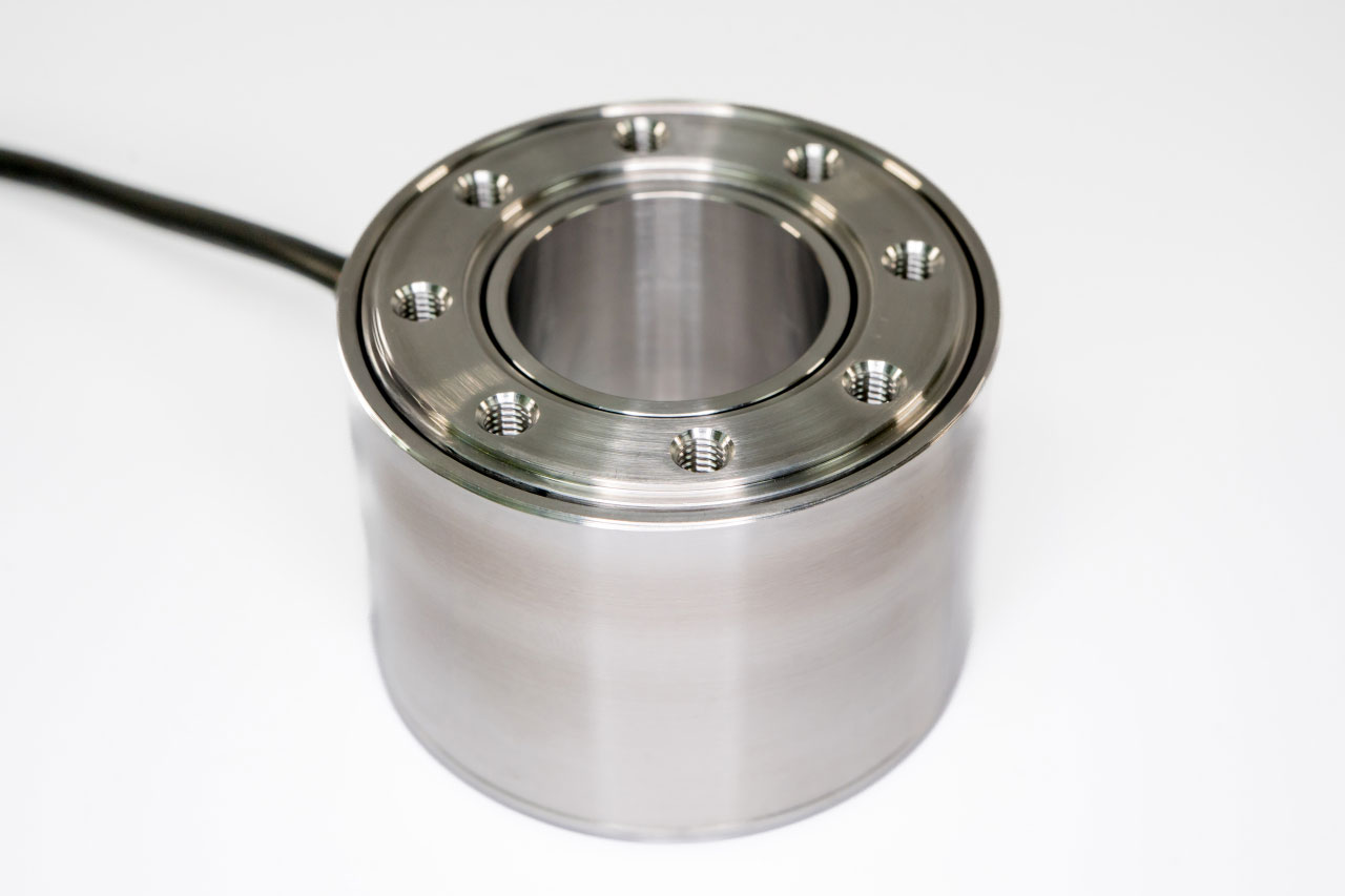
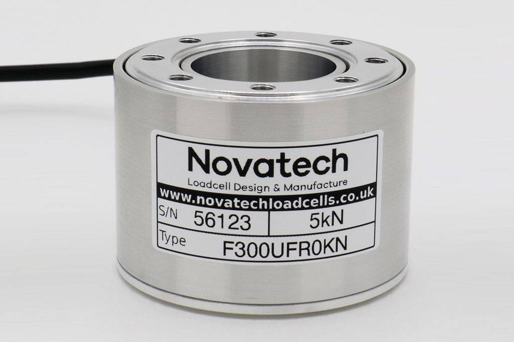
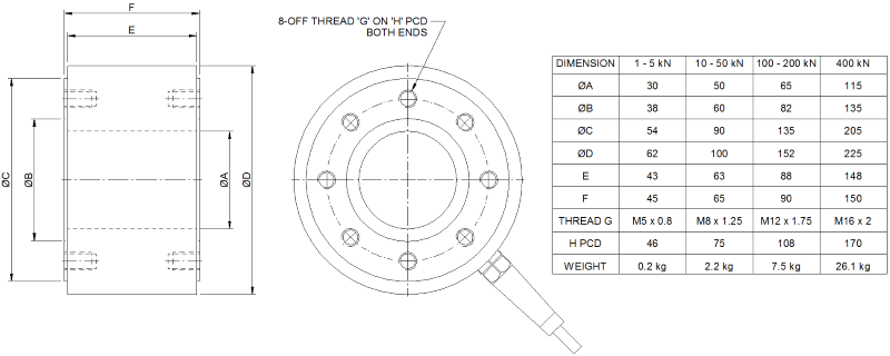
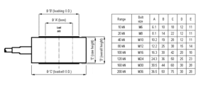
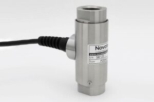
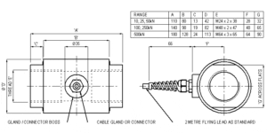
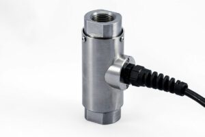
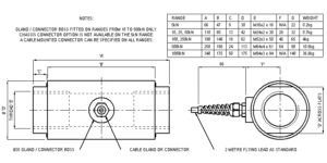
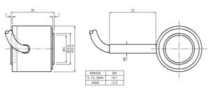
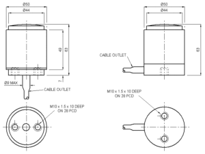
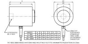
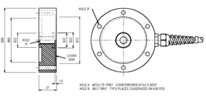
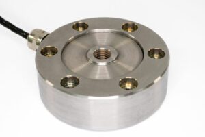
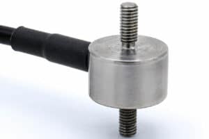
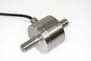
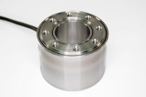
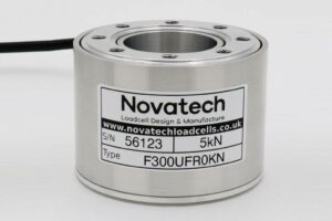
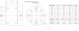
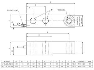
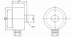
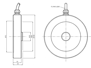
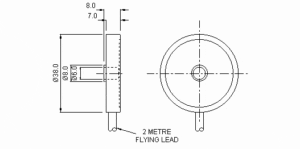
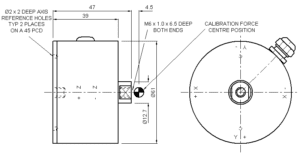
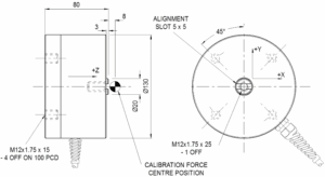
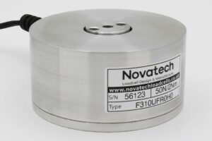
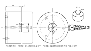
For ranges up to 50kN the loadcell is fitted with 2 metres of PVC insulated 4 core screened cable type 7-2-4C. Ranges above 50kN are fitted with 16-2-4C cable.

Excitation + = Red, Excitation - = Blue, Signal + = Yellow, Signal - = Green, Screen = Orange.

Reverse the signal connections to obtain a positive signal in tension mode. The screen is not connected to the loadcell body.

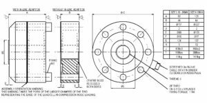
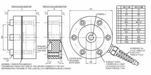
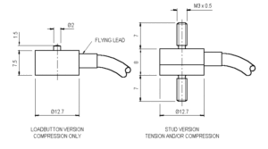
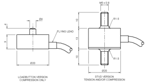
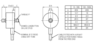
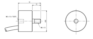
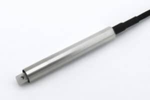
For rationalised ranges up to 5kN the resistors are housed in a capsule located in the loadcell cable 100mm from the free end. Capsule dimensions are Ø10mm by 57mm.

Files

Type

Title

Download

Outline

Outline drawing of the product.

Download

STEP File

F300-T/C/U-FR0KN 1 to 5kN (100 to 500kgf)

Download

STEP File

F300-T/C/U-FR0KN 10 to 50kN (1 to 5tonnef)

Download

STEP File

F300-T/C/U-FR0KN 100 to 200kN (10 to 20tonnef)

Download

STEP File

F300-T/C/U-FR0KN 400kN (40tonnef)

Download