
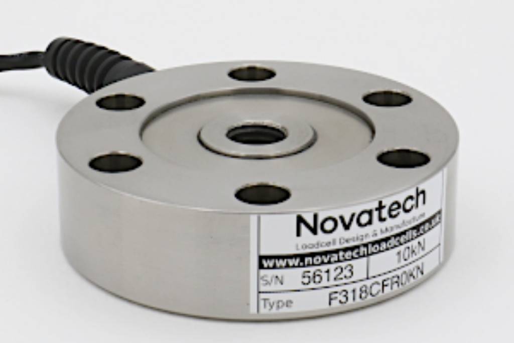
F318 Pancake Loadcell
Standard Ranges 1, 2, 5, 10, 20, 50, 100, 200 and 500kN (100kgf to 50tonnef)
- Tension / compression / bi-directional calibration
- Low profile with recessed centre boss
- Fatigue rated on ranges 10kN and above
- Sealed to IP65
- Hardened stainless steel construction
- Traceable calibration with certificate included in the standard price
Specification
Parameter | Value | Unit |
Non-linearity - Terminal | ±0.1 | % RL |
Hysteresis | ±0.1 | % RL |
Creep - 20 minutes | ±0.05 | % AL |
Repeatability | ±0.02 | % RL |
Rated output - Nominal | 2.1 | mV/V |
Rated output - Rationalised | 2 | mV/V |
Rationalisation tolerance (applies to single direction calibrations) | ±0.1 | % RL |
Output symmetry | ±0.5 | % AO |
Fatigue life (ranges 10kN and above) | 108 | RL cycles |
Zero load output | ±4 | % RL |
Temperature effect on rated output per °C | ±0.005 | % AL |
Temperature effect on zero load output per °C | ±0.005 | % RL |
Temperature range - Compensated | -10 to +50 | °C |
Temperature range - Safe | -10 to +80 | °C |
Excitation voltage - Recommended | 10 | V |
Excitation voltage - Maximum | 20 | V |
Bridge resistance | 700 | Ω |
Insulation resistance - Minimum at 50Vdc | 500 | MΩ |
Fixing bolt torque | See outline drawings. | Nm |
Overload - Safe | 50 | % RL |
Overload - Ultimate | 200 | % RL |
Sealing | IP65 |
All standard ranges are manufactured in stainless steel.
Geometry: Shear web structure with high axial and lateral mechanical stiffness.
The loadcell has good output symmetry between compression and tension operation. All standard bi-directional loadcells are calibrated in both modes.
Ranges up to 20kN have counter bored and tapped outer fixing holes enabling versatile fixing options without loss of the low height advantage.
The F318 pancake loadcell has a recessed boss. If you require a raised boss the F254 may be more suitable. The F254 has standard ranges from 25 to 200kN.
We are happy to design variants of this loadcell to meet your specific requirements. Versions can be manufactured for fully compensated operation up to +250°C. Please consult our engineering department. Details of our other loadcell families can be found in the Loadcell Specifier Guide.
Order Codes
Code | Description |
F318CFR0K0 | Compression, IP65, unrationalised |
F318TFR0K0 | Tension, IP65, unrationalised |
F318UFR0K0 | Bi-directional, IP65, unrationalised |
F318CFR0KN | Compression, IP65, rationalised |
F318TFR0KN | Tension, IP65, rationalised |
F318UFR0KN | Bi-directional, IP65, rationalised |
Change the F to a P for the connector version. | |
Structural Stiffness - Nominal
Range (kN) | Stiffness (N/m) |
1 | 1.6 x 10⁷ |
2 | 1.1 x 10⁸ |
5 | 3.8 x 10⁸ |
10 | 1.6 x 10⁹ |
20 | 1.3 x 10⁹ |
50 | 1.9 x 10⁹ |
100 | 4.5 x 10⁹ |
200 | 9.5 x 10⁹ |
500 | 1.3 x 10¹⁰ |
Notes
- AL = Applied load.
- RL = Rated load.
- AO = Average of tension and compression outputs for full load.
- Temperature coefficients apply over the compensated range.
Connections
The loadcell is fitted with 2 metres of PVC insulated 4 core screened cable type 7-2-4C for ranges up to 20kN. Ranges above 20kN are fitted with 16-2-4C cable. A 4 pin Binder chassis plug option is available instead of the cable. For the ranges up to 20kN the plugs are 712 series, for 50kN and above 723 series are used.
Excitation + = Red or pin 1, Excitation - = Blue or pin 2, Signal + = Yellow or pin 3, Signal - = Green or pin 4, Screen = Orange.
Reverse the signal connections to obtain a positive signal in tension mode. The screen is not connected to the loadcell body.
Files
Type | Title | Download |
Outline | Outline drawing of F318 size 1 and 2. (1 to 20kN.) | |
Outline | Outline drawing of F318 size 3 and 4. (50 to 500kN.) | |
Fittings | Socket plates. | |
Fittings | Loadbutton | |
STEP File | F318-T/C/U-FR0K0 1 to 5kN (100 to 500kgf) | |
STEP File | F318-T/C/U-FR0K0 10 to 20kN (1 to 2tonnef) | |
STEP File | F318-T/C/U-FR0K0 50 to 200kN (5 to 20tonnef) | |
STEP File | F318-T/C/U-FR0K0 500kN (50tonnef) | |
STEP File | F318-T/C/U-PR0K0 1 to 5kN (100 to 500kgf) | |
STEP File | F318-T/C/U-PR0K0 10 to 20kN (1 to 2tonnef) | |
STEP File | F318-T/C/U-PR0K0 50 to 200kN (5 to 20tonnef) | |
STEP File | F318-T/C/U-PR0K0 500kN (50tonnef) | |
STEP File | F318 In-line adaptor 1 to 5kN (100 to 500kgf) | |
STEP File | F318 In-line adaptor 10 to 20kN (1 to 2tonnef) | |
STEP File | F318 In-line adaptor 50 to 200kN (5 to 20tonnef) | |
STEP File | F318 In-line adaptor 500kN (50tonnef) | |
STEP File | F318 Loadbutton 1 to 5kN (100 to 500kgf) | |
STEP File | F318 Loadbutton 10 to 20kN (1 to 2tonnef) | |
STEP File | F318 Loadbutton 50 to 200kN (5 to 20tonnef) | |
STEP File | F318 Loadbutton 500kN (50tonnef) | |
STEP File | F318 Socket plate 1 to 5kN (100 to 500kgf) | |
STEP File | F318 Socket plate 10 to 20kN (1 to 2tonnef) | |
STEP File | F318 Socket plate 50 to 200kN (5 to 20tonnef) | |
STEP File | F318 Socket plate 500kN (50tonnef) |