
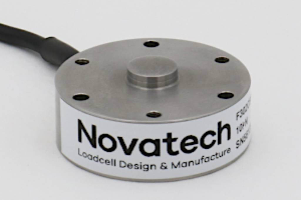
F302 Low Profile Diaphragm Loadcell
Standard Ranges 5, 10, 25 and 50kN (500kgf to 5tonnef)
- Very low profile
- Universal fixing
- Hardened stainless steel
- Sealed to IP65
- Traceable calibration with certificate included in the standard price
- Standard 1 year warranty
Specification
Parameter | Value | Unit |
Non-linearity - Terminal | ±0.5 | % RL |
Hysteresis | ±0.3 | % RL |
Creep - 20 minutes | ±0.05 | % AL |
Repeatability | ±0.1 | % RL |
Rated output - Rationalised | 2.0 | mV/V |
Rationalisation tolerance | ±0.5 | % RL |
Zero load output | ±4 | % RL |
Temperature effect on rated output per °C | ±0.005 | % AL |
Temperature effect on zero load output per °C | ±0.005 | % RL |
Temperature range - Compensated | -10 to +50 | °C |
Temperature range - Safe | -10 to +80 | °C |
Excitation voltage - Recommended | 10 | V |
Excitation voltage - Maximum | 10 | V |
Bridge resistance | 350 | Ω |
Insulation resistance - Minimum at 50Vdc | 500 | MΩ |
Overload - Safe | 50 | % RL |
Overload - Ultimate | 300 | % RL |
Sealing | IP65 | |
Weight - Nominal (excluding cable) | 78 to 90 | g |
All standard ranges are manufactured in stainless steel.
Geometry: Low profile axial loadcell for use in force measurements in compression.
The F302 is designed for force measurement in compression. The loadcell is designed for simple mounting on a smooth flat surface. It has an integral load button and is supplied with three tapped holes and three clearance holes enabling fixing or location from either above or below the loadcell.
In the event of structural failure of the loadcell the resulting vertical movement of the supported load will be very small.
We are happy to design variants of this loadcell to meet your specific requirements. Please consult our engineering department.
Order Codes
Code | Description |
F302CFROHN | Compression, IP65, rationalised |
Structural Stiffness - Nominal
Range (kN) | Stiffness (N/m) |
5 | 1.0 x 10⁸ |
10 | 2.9 x 10⁸ |
25 | 1.1 x 10⁹ |
50 | 2.2 x 10⁹ |
Notes
- AL = Applied load.
- RL = Rated load.
- Temperature coefficients apply over the compensated range.
- The load must be applied directly through the central loading axis.
Connections
The loadcell is fitted with 2 metres of PVC insulated 4 core screened cable type 7-1-4C.
Excitation + = Red, Excitation - = Blue, Signal + = Yellow, Signal - = Green, Screen = Orange.
The screen is not connected to the loadcell body.
When this loadcell is rationalised the resistors are housed in a capsule located in the loadcell cable 100mm from the free end. Capsule dimensions are Ø10mm by 57mm.