
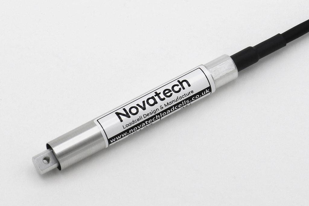
F301 Low Range Stylus Loadcell
Standard Ranges 1 and 3N (100 and 300gf)
- Integral overload stops
- Tension / compression / bi-directional calibration
- Simple installation
- Small diameter
- Traceable calibration with certificate included in the standard price
- Standard 1 year warranty
Specification
Parameter | Value | Unit |
Non-linearity - Terminal | ±0.1 | % RL |
Hysteresis | ±0.1 | % RL |
Creep - 20 minutes | ±0.05 | % AL |
Repeatability | ±0.03 | % RL |
Rated output - Nominal | 1.0 | mV/V |
Rated output - Rationalised | 0.8 | mV/V |
Rationalisation tolerance (applies to single direction calibrations) | 0.5 | % RL |
Zero load output | ±8 | % RL |
Temperature effect on rated output per °C | ±0.005 | % AL |
Temperature effect on zero load output per °C | ±0.01 | % RL |
Temperature range - Compensated | -10 to +50 | °C |
Temperature range - Safe | -10 to +80 | °C |
Excitation voltage - Recommended | 10 | V |
Excitation voltage - Maximum | 10 | V |
Bridge resistance | 350 | Ω |
Insulation resistance - Minimum at 50Vdc | 500 | MΩ |
Overload - Safe | 20 | % RL |
Overload - Ultimate | 100 | % RL |
Weight - Nominal (excluding cable) | 18 to 20 | g |
All standard ranges are manufactured in aluminium.
The F301 is a compact bending beam loadcell for low range force measurements. Its small diameter eases mounting problems in existing systems. All standard bi-directional loadcells are calibrated in both modes.
The loadcell has integral overload stops to protect against overloading in the vertical axis. Torsional loads about the longitudinal axis may damage the loadcell.
We are happy to design variants of this loadcell to meet your specific requirements. Versions can be manufactured for higher temperature operation. Please consult our engineering department.
Order Codes
Code | Description |
F301CF00H0 | Compression, unrationalised |
F301TF00H0 | Tension, unrationalised |
F301UF00H0 | Bi-directional, unrationalised |
F301CF00HN | Compression, rationalised |
F301TF00HN | Tension, rationalised |
F301UF00HN | Bi-directional, rationalised |
Structural Stiffness - Nominal
Range (N) | Stiffness (N/m) |
1 | 1.2 x 10³ |
3 | 3.6 x 10³ |
Notes
- AL = Applied load.
- RL = Rated load.
- Temperature coefficients apply over the compensated range.
- The load must be applied directly through the central loading axis.
Connections
The loadcell is fitted with 2 metres of PVC insulated 4 core screened cable type 7-1-4C.
Excitation + = Red, Excitation - = Blue, Signal + = Yellow, Signal - = Green, Screen = Orange.
Reverse the signal connections to obtain a positive signal in tension mode. The screen is not connected to the loadcell body.
When this loadcell is rationalised the resistors are housed in a capsule located in the loadcell cable 100mm from the free end. Capsule dimensions are Ø10mm by 57mm.