The F328 is a universal axial loadcell that has been specifically designed for immunity to large extraneous forces, particularly in comparison to the sensor’s very low rated load.
As shown in Engineering Application Sheet E003: Loadcell Range Selection, all loadcells will be most accurate when used nearest to their full rated load. The intended purpose of the F328 loadcell is, therefore, to provide accurate low range force measurement for precision applications such as those found in medical sciences and biometrics for example. Its high resistance 5000Ω strain gauge bridge also makes this loadcell ideal for any battery powered applications, such as those using a laptop computer with a DSC USB loadcell digitiser or a hand held TR150 loadmeter.
To ensure maximum sensitivity, the strain system for a low range force sensor would typically tend towards being an extremely delicate structure. This would make the loadcell inherently prone to off axis loading and sideload induced errors. Worse still, these extraneous loads could potentially damage the delicate sensing elements, limiting the loadcell’s usefulness to applications in which the force input is precisely aligned and controlled. To counter act this, the F328 exploits a laminated structure to produce excellent extraneous force and moment rejection, together with minimal translational deflection, in order to provide both accuracy and robustness.
Moments can be particularly detrimental in force measurement and will often heavily influence the output from a standard bridge circuit. Worse still, it is possible to have a large moment without being fully aware of the extent of the problem, as even a small sideload at a reasonable distance can cause a sizeable moment. For this reason, it is desirable to have known and predictable behaviour with respect to applied sideloads and moments.
For the F328 loadcell we are able to give the following extraneous force characteristics that are true across the entire standard datasheet range:
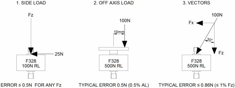
- A sideload of up to 25%RL will result in less than 0.5%RL error.
- An off-axis load of up to 100%RL applied anywhere within the loadcell footprint will result in less than 0.5%AL error.
- Vectors up to 30° off axis will result in less than 1%AL error. *
- Maximum permissible sideload 40%RL.
- Maximum permissible moment arm for off axis loads 25mm in any direction, for up to the RL.
- For moment induced errors use the off-axis and side load rules for guidance.
* This relates to the magnitude of error that is unaccounted for after removing cosine errors. Cosine errors can be mathematically accounted for and compensated as shown below.
For extraneous load definitions see Engineering Sheet E036.
The information given above concerns the maximum possible error figures only. From extensive testing it has been found that certain orientations will tend to provide superior error compensation due to the compound effect of beam symmetry, gauge alignment and machining tolerance. Similarly, any individual loadcell may far exceed the extraneous force immunity performance stated in any orientation for the same reasons.
When installing an F328 loadcell, it should be noted that improper or careless handling can result in forces exceeding either the rated load of the loadcell or its extraneous force capacity. This is particularly true of the lower ranges such as the 10N loadcell. The live stud should never be held directly between fingers and the use of tools should be kept to a minimum. Both the live and earth stud have a small boss to ensure that fixings cannot come into direct contact with the loadcell body, although lock nuts should still be used where possible to ensure datasheet performance. When tightening locknuts or other fixings, excessive torque should be avoided and it is best to limit the mechanical advantage available by using as small a spanner as possible. Although the loadcell will always show a noticeable zero-shift before a critical load is applied, temporary zero shift can occur from handling due to uneven heat exchange through the case. An F328 should be left to sit for a few minutes after installation before taking an initial zero reading.
Error Evaluation in Detail
Error evaluation for the F328 loadcell was conducted in accordance to a strict methodology. A number of loadcells of varying ranges were calibrated to our usual high standards to obtain control data, before being subjected to a fixed percentage of their ultimate extraneous force capacity. A dedicated rig was used to apply all combinations of extraneous forces and the resulting data was tabulated and manipulated using straight line maths. In the case of the vector tests, the unavoidable cosine error was calculated and separated from the loadcell specific measurement error. The vector analysis between ±15° for a typical 500N loadcell under 25%RL is shown below.
Vector Analysis For A Typical 500N F328 Loadcell
| Angle
(deg) |
Axial Component (N) |
Sideload Component (N) |
Expected Output (mV/V) |
Actual Output (mV/V) |
Total Error (%AL) |
Cosine Error (%AL) |
Loadcell Error (%AL) |
| -15 | 120.74 | 32.35 | 0.28759 | 0.28620 | 3.88 | 3.41 | 0.47 |
| -10 | 123.10 | 21.71 | 0.29322 | 0.29230 | 1.83 | 1.52 | 0.31 |
| -5 | 124.52 | 10.89 | 0.29661 | 0.29612 | 0.54 | 0.38 | 0.16 |
| 0 | 125 | 0 | 0.29774 | 0.29774 | 0 | 0 | 0 |
| 5 | 124.52 | 10.89 | 0.29661 | 0.29614 | 0.54 | 0.38 | 0.16 |
| 10 | 123.10 | 21.71 | 0.29322 | 0.29234 | 1.81 | 1.52 | 0.29 |
| 15 | 120.74 | 32.35 | 0.28759 | 0.28630 | 3.84 | 3.41 | 0.43 |
Increasing the vector angle results in a marked reduction in the pure axial force component and an increase in the sideload component. This reduction in the axial force is referred to as a cosine error as it is a simple cosine function of the vector angle. In an application involving large vector angles, a multi-axis loadcell might be a good solution as there is effectively no error other than cross-talk, as both components are actively measured. Where a multi-axis loadcell is not appropriate however, an axial loadcell will not only see less measurable force due to cosine error but will also present a measure of sideload induced error. Removing the cosine error in this manner is an acceptable form of error manipulation as the remaining error is specific to the loadcell and gives an accurate representation of the extraneous force immunity of the sensor. From the characteristics given earlier, it can be seen that the F328 is an extremely good choice for where excellent extraneous force immunity is required in order to allow accurate low force measurement in a complex force system.
AL = Applied load. RL = Rated load.