
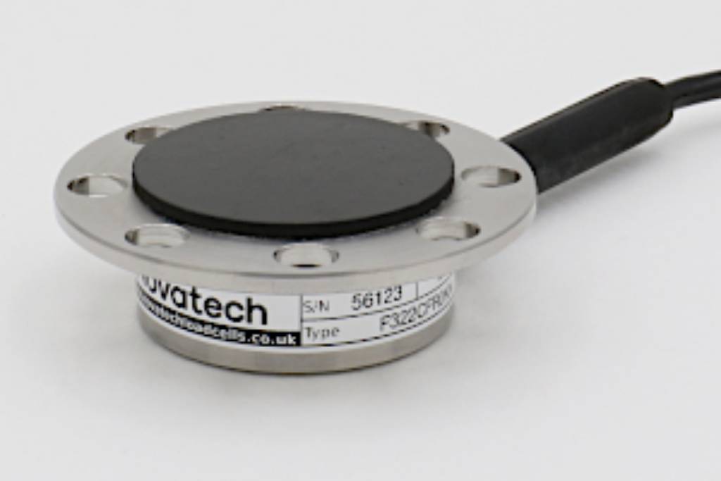
F322 Accelerator Pedal Force Loadcell
Standard Range 250N (25kgf)
- Off centre loading compensation
- Simple cable tie or screw fixing
- Anti-slip rubber pad
- Removable loading plate
- Output rationalised to 1mV/V
- Lightweight aluminium alloy construction
- Traceable calibration with certificate included in the standard price
Specification
Parameter | Value | Unit |
Non-linearity - Terminal | ±0.05 | % RL |
Hysteresis | ±0.05 | % RL |
Creep - 20 minutes | ±0.05 | % AL |
Repeatability | ±0.02 | % RL |
Rated output - Rationalised | 1.0 | mV/V |
Rationalisation tolerance | ±0.1 | % RL |
Zero load output | ±10 | % RL |
Temperature effect on rated output per °C | ±0.005 | % AL |
Temperature effect on zero load output per °C | ±0.01 | % RL |
Temperature range - Compensated | -10 to +50 | °C |
Temperature range - Safe | -10 to +80 | °C |
Excitation voltage - Recommended | 10 | V |
Excitation voltage - Maximum | 20 | V |
Bridge resistance | 700 | Ω |
Insulation resistance - Minimum at 50Vdc | 500 | MΩ |
Inclined load error - concentric at 3° | ±0.25 | % RL |
Structural stiffness | 8 x 10⁶ | N/m |
Overload - Safe | 50 | % RL |
Overload - Ultimate | 200 | % RL |
Sideload - Safe | 100 | % RL |
Sealing | IP65 | |
Weight - Nominal (excluding cable) | 80 | g |
The standard range is manufactured in aluminium.
The F322 is a compact, low profile loadcell for measuring accelerator pedal application forces.
The loadcell is robust in construction with a maximum force range of 250N (25kgf). Its multi-hole fixing allows simple attachment to any shape pedal using screws or cable ties. The low profile design maintains the accelerator pedals ergonomic geometry. Low mass aluminium alloy construction reduces the mass influence upon the accelerator pedal in dynamic testing.
If you require other force ranges the F304 or F323 may be suitable.
We are happy to design variants of this loadcell to meet your specific requirements.
Order Codes
Code | Description |
F322CFR0KN | Compression, IP65, rationalised |
Notes
- AL = Applied load.
- RL = Rated load.
- Temperature coefficients apply over the compensated range.
Connections
The loadcell is fitted with 2 metres of flexible polyurethane jacketed 4 core screened cable.
Excitation + = Red, Excitation - = Blue, Signal + = Yellow, Signal - = Green, Screen = Orange.
The screen is not connected to the loadcell body.
When this loadcell is rationalised the resistors are housed in a capsule located in the loadcell cable 100mm from the free end. Capsule dimensions are Ø10mm by 57mm.