Home » Products
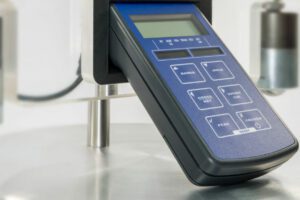
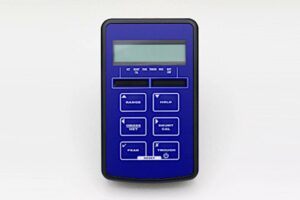
The TR150 is a completely portable, precision instrument packaged in a small, robust IP65 (NEMA 4) enclosure, weighing only 260 grams. The TR150 accepts an input range of up to 50mV/V.
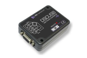
The DSC USB is a compact, high performance digital signal conditioner with USB connectivity aimed at applications, which require high-accuracy measurement repeatability.
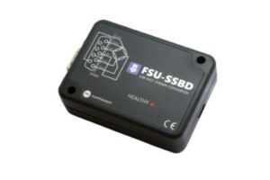
The FSU-SSBD is a fast, compact, high precision loadcell input module delivering high resolution readings over USB and communicated directly to a PC.
The SGA loadcell amplifier is designed for use with strain gauge loadcells. It provides industry standard current or voltage outputs for accurate interfacing of loadcells with control and monitoring systems.
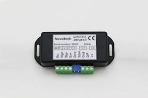
This miniature loadcell amplifier is designed for use with strain gauge loadcells. It has a bi-polar ±10V output for use with bi-directional loadcells even though it is powered from a uni-polar supply.
The LCA15 has been redesigned to become the LCA20 taking advantage of new technology to improve performance and increase functionality.
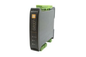
The LCD20 intelligent loadcell amplifier is a compact, DIN rail mounted microprocessor based unit for use with strain gauge bridge loadcells in force measuring applications.
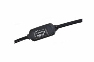
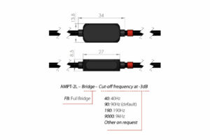
Compact , in-line, cable mounted amplifier with 12V supply and 0-5V output. Particularly popular for automotive applications.
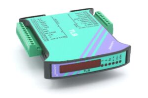
TLB DIN rail mounted digital loadcell amplifier
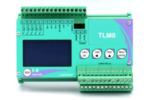
TLM8 Multi-input digital loadmeter
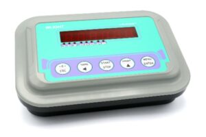
WLIGHT portable digital loadmeter
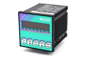
W200 digital loadmeter
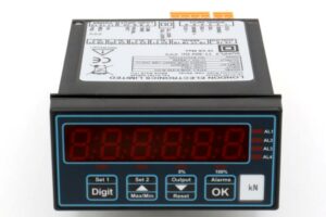
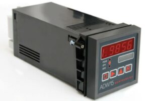
The versatile INT4-L panel mount loadmeter for strain gauge loadcells
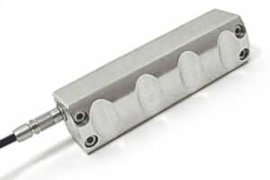
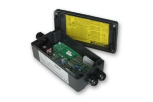
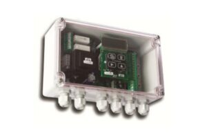
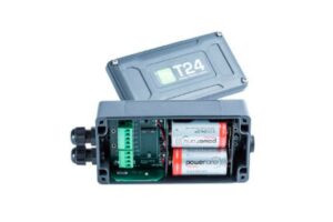
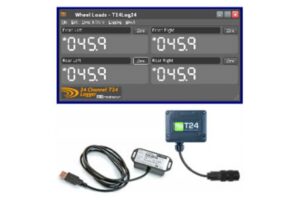
This remote loadcell data acquisition unit provides high performance wireless measurement of loadcell outputs. Providing direct mV/V input and 5V bridge excitation for up to 4 load cells.
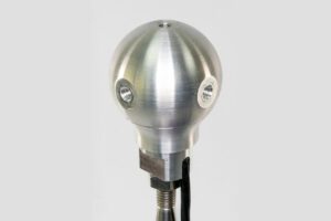
This miniature loadcell data acquisition unit provides high performance wireless measurement of loadcell outputs. Providing direct mV/V input and 5V bridge excitation for up to 4 load cells.
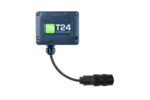
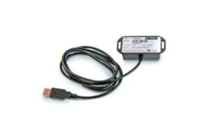
The base station is a computer interface for the T24 telemetry system that connects to a standard USB port on a computer. It is required for the configuration of all T24 modules.
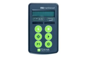
This wireless handheld display module provides an 8 digit LCD reading from up to twelve T24 loadcell data acquisition modules.
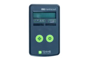
This wireless handheld display module provides an 8 digit LCD reading from a T24 loadcell data acquisition module.
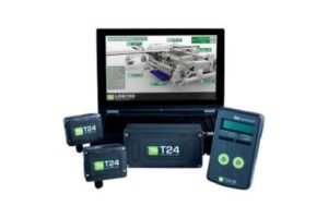
The T24 telemetry range is a flexible radio telemetry system designed to provide high accuracy measurement data from strain gauge loadcells.
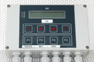
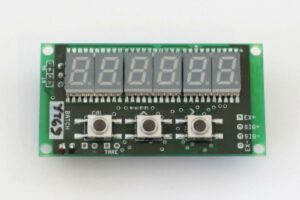
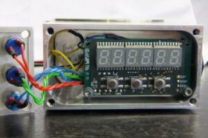
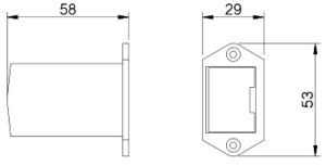
This panel or wall mounting loadmeter is designed for use with strain gauge loadcells.
This intelligent self contained loadmeter is designed for use with strain gauge loadcells.
This loadcell amplifier is designed for use with strain gauge loadcells.
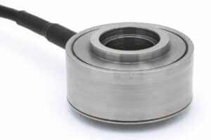
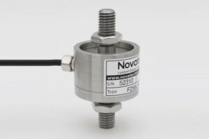
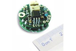
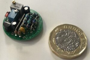
This loadcell amplifier is designed for mounting inside the F256 and F257 loadcells.
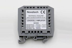
This DIN rail mounted loadcell amplifier is designed for use with strain gauge loadcells.
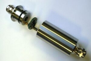
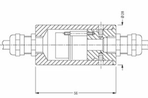
This small loadmeter is designed for mounting in modified strain gauge loadcells.