
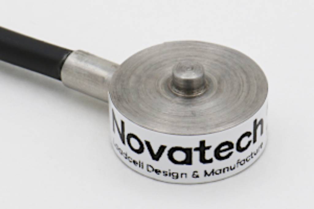
F250 Miniature Diaphragm Loadcell
Standard Ranges 100, 200, 400 and 800N (10 to 80kgf)
- Tension / compression / bi-directional calibration
- Easy installation
- 15mm diameter
- Hardened stainless steel construction
- Traceable calibration with certificate included in the standard price
- Standard 1 year warranty
Specification
Parameter | Value | Unit |
Non-linearity - Terminal | ±0.5 | % RL |
Hysteresis | ±0.5 | % RL |
Creep - 20 minutes | ±0.1 | % AL |
Repeatability | ±0.1 | % RL |
Rated output - Nominal | 1.6 | mV/V |
Rated output - Rationalised | 1.0 | mV/V |
Rationalisation tolerance (applies to single direction calibrations) | ±0.5 | % RL |
Zero load output | ±4 | % RL |
Temperature effect on rated output per °C | ±0.005 | % AL |
Temperature effect on zero load output per °C | ±0.03 | % RL |
Temperature range - Compensated | -10 to +50 | °C |
Temperature range - Safe | -10 to +80 | °C |
Excitation voltage - Recommended | 5 | V |
Excitation voltage - Maximum | 10 | V |
Bridge resistance | 350 | Ω |
Insulation resistance - Minimum at 50Vdc | 500 | MΩ |
Overload - Safe | 50 | % RL |
Overload - Ultimate | 100 | % RL |
Sealing | IP65 | |
Weight - Nominal (excluding cable) | 8 to 12 | g |
F250 Miniature Diaphragm Loadcell. Geometry: Very small loadbutton cell for force measurement in confined spaces. Used in compression and/or tension on a wide range of OEM or end-user applications.
With bi-directional versions there is a small difference between the output signal for compression and tension. All standard bi-directional loadcells are calibrated in both modes and the output for each direction is stated on the test / calibration certificate.
The F250 is ideally suited to force measurements in confined spaces in both tension and compression for control of critical parameters in all kinds of industrial processes. Their versatility is such that they are also applied in a great number of important fields of scientific and engineering test work, mobile as well as workshop, static and dynamic.
We are happy to design variants of this loadcell to meet your specific requirements. Please consult our engineering department.
Order Codes
Code | Description |
F250CFR0H0 | Compression, IP65, unrationalised |
F250TFR0H0 | Tension, IP65, unrationalised |
F250UFR0H0 | Bi-directional, IP65, unrationalised |
F250CFR0HN | Compression, IP65, rationalised |
F250TFR0HN | Tension, IP65, rationalised |
F250UFR0HN | Bi-directional, IP65, rationalised |
Change the C to a D for compression with thread fitting. | |
Structural Stiffness - Nominal
Range (N) | Stiffness (N/m) |
100 | 6.2 x 10⁶ |
200 | 1.2 x 10⁷ |
400 | 2.5 x 10⁷ |
800 | 5.0 x 10⁷ |
Notes
- AL = Applied load.
- RL = Rated load.
- Temperature coefficients apply over the compensated range.
- The load must be applied directly through the central loading axis.
Connections
The loadcell is fitted with 2 metres of PVC insulated 4 core screened cable type 7-1-4C.
Excitation + = Red, Excitation - = Blue, Signal + = Yellow, Signal - = Green, Screen = Orange.
Reverse the signal connections to obtain a positive signal in tension mode. The screen is not connected to the loadcell body.
When this loadcell is rationalised the resistors are housed in a capsule located in the loadcell cable 100mm from the free end. Capsule dimensions are Ø10mm by 57mm.