
F232/3 Multi-Axis Loadcell
Ranges 100N to 5kN (10 to 500kgf)
- 2 & 3 axis versions
- Custom force ranges
- Simple installation
- Direct output from each axis without calculation
- Traceable calibration with certificate included in the standard price
- Standard 1 year warranty
Specification
Parameter | Value | Unit |
Non-linearity - Terminal | ±0.5 | % RL |
Hysteresis | ±0.5 | % RL |
Creep - 20 minutes | ±0.1 | % AL |
Repeatability | ±0.02 | % RL |
Maximum cross talk | 3 | % RL |
Calibration force centre | x=0, y=0, z=-4.5 | mm |
Rated output - Nominal | 1.2 | mV/V |
Zero load output | ±4 | % RL |
Temperature effect on rated output per °C | ±0.005 | % AL |
Temperature effect on zero load output per °C | ±0.01 | % RL |
Temperature range - Compensated | -10 to +50 | °C |
Temperature range - Safe | -10 to +80 | °C |
Excitation voltage - Recommended | 10 | V |
Excitation voltage - Maximum | 10 | V |
Bridge resistance X & Y axis | 350 | Ω |
Z axis | 700 | Ω |
Insulation resistance - Minimum at 50Vdc | 500 | MΩ |
Overload - Safe | 50 | % RL |
Overload - Ultimate | 100 | % RL |
Weight - Nominal (excluding cable) | 200 | g |
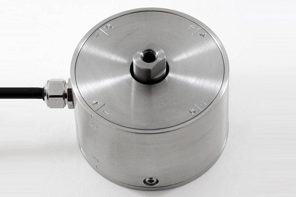
The F232 measures forces in two axes at 90° and the F233 measures forces in 3 mutually perpendicular axes. Apart from error evaluations, each output is pure and requires no mathematical manipulation.
The loadcell is moment sensitive requiring calibration to be carried out at a specified force centre. The standard centre is specified in the specification. If this is not suitable for your application please consult our engineering department about alternative calibrations.
The F232/3 is ideally suited to many industrial and scientific applications, including automotive and medical research.
The loadcell can be manufactured with force ranges to suit the application. The Z axis can have a different force range from the X and Y axes. Please consult our engineering department about the viability of the required ranges. The example shown in the picture and drawing is a 500N model; there will be small differences in the dimensions for other ranges.
We are happy to design variants of this loadcell to meet your specific requirements. Other types of multi-axis loadcell can be supplied with ranges up to 20kN. Versions can be manufactured for higher temperature operation. Please consult our engineering department.
Additional information on specifying a multi-axis loadcell can be found in Engineering Sheet E015.
Order Codes
Code | Description |
Most F232/3 loadcells are manufactured to special requirements and are given an F232-Zxxxx or F233-Zxxxx number. | |
Structural Stiffness - Nominal
Range (kN) | Stiffness (N/m) |
100 N (per axis) | |
5 kN (per axis) |
Notes
- AL = Applied load.
- RL = Rated load.
- Temperature coefficients apply over the compensated range.
- Values apply to all axes unless otherwise specified.
Connections
The F232 is fitted with 2 metres of PVC insulated 9 core screened cable type 7-1-9C. The F233 is fitted with 2 metres of PVC insulated 12 core screened cable type 7-1-12C. The screen is not connected to the loadcell body.
| Function | Wire Colour | ||
| X axis | Y axis | Z axis | |
|---|---|---|---|
| Excitation + | Red | Violet | Orange |
| Excitation - | Blue | Black | Turquoise |
| Signal + | Yellow | Brown | Pink |
| Signal - | Green | White | Grey |
| Screen | Orange (thick) |